Wednesday 28 August 2013

Introduction to the PC busses

Introduction to the PC busses
The PC receives and sends its data from and to busses. They can be divided into:
l   The system bus, which connects the CPU with RAM
l   I/O busses, which connect the CPU with other components.
The point is, that the system bus is the central bus. Actually, it connects to the I/O busses, as
An illustrated Guide to the PC System BUS
file:///E|/education/Click & Learn/module2b.htm (3 of 8) [4/15/1999 6:17:39 AM]
you can see in this illustration:
You see the central system bus, which connects the CPU with RAM. A bridge connects the I/O
busses with the system bus and on to RAM. The bridge is part of the PC chip set, which will be
covered in module 2c.
3 different I/O busses
The I/O busses move data. They connect all I/O devices with the CPU and RAM. I/O devices are
those components, which can receive or send data (disk drives, monitor, keyboard, etc. ). In a
modern Pentium driven PC, there are two or three different I/O busses:
l   The ISA bus, which is oldest, simplest, and slowest bus.
l   The PCI bus, which is the fastest and most powerful bus.
l   The USB bus, which is the newest bus. It may in the long run replace the ISA bus.
The three I/O busses will be described later. Here, we will take a closer look at the PC's
fundamental bus, which the others are branches from:
The system bus
The system bus connects the CPU with RAM and maybe a buffer memory (L2-cache). The
An illustrated Guide to the PC System BUS
system bus is the central bus. Other busses branch off from it.
The system bus is on the system board. It is designed to match a specific type of CPU.
Processor technology determines dimensioning of the system bus. At the same time, it has taken
much technological development to speed up "traffic" on the system board. The faster the
system bus gets, the faster the remainder of the electronic components must be..
The following three tables show different CPU's and their system busses:

We see, that system bus speed follows the CPU's speed limitation. First at the fourth generation
CPU 80486DX2-50 are doubled clock speeds utilized. That gives the CPU a higher internal clock
frequency. The external clock frequency, used in the system bus, is only half of the internal
frequency
66 MHz bus


Tuesday 27 August 2013

The data flow on the system board

The data flow on the system board
On the system board, you will find the CPU, which is the "brain" of the PC and the busses. The
busses are the nerve system of of system board. They connect the CPU to all the other
components. There are at least three busses, which you can see below. You can read more
about those on the following pages.
The busses are the PC's expressways. They are "wires" on the circuit board, which
transmit data between different components. One "wire" can move one bit at a time.
l   
In the following text, we start from a modern Pentium board. We will look at busses, chip sets
and CPU's. Here is an illustration of the system board "logic," which you can print out.
An illustrated Guide to the PC System BUS

Here, you can switch to read about what data really are. Or click to move to the page about the
CPU. Or read more about data, and how they are saved in the PC file systems. 

The boot process

The boot process
The last step in the PC start-up is reading the operating system. The start-up program is
instructed to find the Master boot sector. The boot sector is the very first sector on either hard
disk (C) or floppy drive A.
By default, the PC will look for a boot sector in floppy drive A. That is why the PC "drops dead" if
there is a different diskette in A drive. If there is no diskette in A drive, the start-up program will
search for the boot sector on hard drive C. When the boot sector is found, a small program
segment (boot-strap) is read from there. The boot-strap then takes over control of the PC. The
start-up program has done its job. Now DOS, Windows, or another operating system takes
control.


The BIOS programs

The BIOS programs
During start-up. the BIOS programs are read from a ROM chip. BIOS is abbreviation of Basic Input Output System and those
are programs, which are linked to specific hardware systems. For example, there is a BIOS routine, which identifies how the
PC reads input from the keyboard.
BIOS is a typical link in the IBM compatible PC design. The BIOS programs control hardware, the user (programmer) controls
hardware via a call to BIOS.
BIOS typically occupy 1 MB, and the programs are saved ROM chips on the system board.
During start-up, BIOS is read from ROM chips. That information is supplemented with the system data saved in CMOS.
Furthermore, there is BIOS code on the expansion cards. The expansion cards are external hardware, as interpreted by the
system board, and the BIOS code, which is linked to the expansion card, must be included in the configuration. Therefore,
this expansion card ROM is read during start-up, and the program code is woven together with other BIOS data. It is all
written into RAM, where it is ready for the operating system, as you can see here:
Otherwise, the BIOS routines are not always in use. They can be regarded as basic program layers in the PC. Many
programs routinely bypass BIOS. In that case, they "write direct to hardware", as we say. Windows contains program files,
which can be written directly to all kinds of hardware - bypassing BIOS routines. One example is the COM ports. If you use
the BIOS routines connected with them, you can transmit only at max. 9600 baud on the modem. That is insufficient.
Therefore, Windows will assume control over the COM port.
BIOS-update
BIOS programs can be updated. The modern system board has the BIOS instructions in flash-ROM, which can be updated.
You can get new BIOS-software from your supplier or on the Internet, which can be read onto the system board. The loading
is a special process, where you might need to change a jumper switch on the system board. Usually, you do not need to do
this, but it is a nice available option.
ATX
The latest PC electronic standard is called ATX. It consists of a new type system board with a specific physical design smaller
than the traditional board (30.5 cm X 19 cm). The I/O connectors COM1, COM2 and LPT, keyboard, mouse and USB are
mounted directly on the system board. The ATX board requires specifically designed chassis's with an I/O access opening
measuring 1¾ by 6¼ inch. ATX is designed by Intel, but has gained general acceptance.
The ATX system board is more ”intelligent” than the ordinary type. In a few years, it will be wide spread. It includes advanced
control facilities, where the BIOS program continually checks the CPU temperature and voltages, the cooling fans RPM, etc. If
over heating occurs, the PC will shut down automatically. The PC can also be turned on by for example modem signals, since

the power supply is controlled by the system board. The on/off button will turn the PC "down" without turning it completely off.
If you want a PC designed for the future, the ATX layout is what you should go for.

Password Protection

Password Protection
You protect the Setup program with a password. This is used widely in schools, where they do not want the little nerds to
make changes in the setup. Please remember the password (write it down in the mainboard manual). If you forget it you have
to remove the battery from the mainboard. Then all user-input to the CMOS is erased - including the password.
Here is a scanned image from a Setup program. It belongs to my favorite board (from ASUS). Here you see the "BIOS
Feature Setup," where you can select start-up choices:

Here we are are in the special "Chip set Feature Setup." These choices relate to the chip sets and, most likely, need no
changes:
An illustrated Guide to Motherboards

The Setup program

The Setup program
You communicate with the BIOS programs and the CMOS memory through the so-called Setup program.
Typically you reach the Setup program by pressing [Delete] immediately after you power up the PC. That brings you to a
choice of setup menus. You leave Setup by pressing [Esc], and choose "Y" to restart the PC with the new settings. Generally,
you should not change these settings, unless you know precisely what you are doing.
The Setup program can do many things for you. You have to enter Setup, if you install a different type or additional disk drive
in your PC. Certain BIOS's will also need adjustment of its settings, if a CD ROM drive is installed on one of the EIDE
channels.
Modifying the boot sequence
You can change the boot sequence from A:, C: to C:, A:. That means, that the PC will not try to boot from any diskette in the
A drive. That will protect you from certain virus attacks from the boot sector. Also, the boot process will not be blocked by any
diskette in the A drive. If you need to boot from A-drive (for example, if you want to install Windows 97 ), you have to enter
Set-up again, and change the boot sequence to A:, C:. That is no problem.
Power Management
You also use the Setup program to regulate Power Management, which is the power saving features in the system board. For
example, you can make the CPU shut down after one minute of no activity. There are plenty of settings available in this areat

Suppliers of system software

Suppliers of system software
All PC's have instructions in ROM chips on the system board. The ROM chips are supplied by specialty software
manufacturers, who make BIOS chips. The primary suppliers are:
l   Phoenix
l   AMI (American Megatrends)
l   Award
You can read the name of your BIOS chip during start-up. You can also see the chip on the system board. Here is a picture
(slightly blurred) of an Award ROM chip:
Here is an AMI chip with BIOS and start-up instructions:
The

CMOS


CMOS
CMOS (Complimentary Metal Oxide Semiconductor) is a small amount of memory in a special RAM chip. Its memory is
maintained with electric power from a small battery. Certain system data are stored in this chip. They must be read to make
the PC operable. There may be 100 to 200 bytes of data regarding date, time, floppy and hard disk drives, and much more.
CMOS data can be divided in two groups:
l   Data, which POST can not find during the system test.
l   Data, which contain user options.
For example, POST cannot by itself find sufficient information about the floppy drive(s). Floppy drives are so "dumb," that
POST cannot read whether they are floppy drives or not, nor what type. About the same goes for IDE hard disks, while EIDE
hard disks are a little more "intelligent," However, POST still needs assistance to identify them 100% correctly.
The same goes for RAM: POST can count how much RAM is in the PC. However, POST cannot detect whether it is FPM,
EDO or SD RAM. Since the CPU and BIOS reads data from RAM chips differently, depending on the RAM type, that type
must be identified.
Configuration
The PC must be configured, be supplied with this information. That is done in the factory or store, where it is assembled. This
information is stored in CMOS, where they stay. CMOS data only need to be updated, when different or additional hardware
components are installed. This could be a different type hard disk or floppy disks or an new RAM type, Often he user can do
this.
Other data in CMOS contain various user options. Those are data, which you can write to CMOS. For example, you can
adjust date and time, which the PC then adjusts every second. You can also choose between different system parameters.
Maybe you want a short system check instead of a long one. Or if you want the PC to try to boot from hard disk C before
trying floppy disk A, or vice versa. These options can be written to CMOS.
Many of the options are of no interest to the ordinary user. These are options, which regard controller chips on the system
board, which can be configured in different ways. Ordinarily, there is no need to make such changes. The system board
manufacturer has already selected the optimal configurations. They recommend in their manuals, that you do not change
these default settings.
We can conclude, that CMOS data are essential system data, which are vital for operation of the PC. Their special feature isthat they are user adjustable. Adjustments to CMOS are made during start-up.
CMOS BATTERY


POST

POST
Power On Self Test is the first instruction executed during start-up. It checks the PC components and that everything works.
You can recognize it during the RAM test, which occurs as soon as you turn power on.
As users, we have only limited ability to manipulate the POST instructions. But certain system boards enable the user to order
a quick system check. Some enable the user to disable the RAM test, thereby shortening the duration of the POST. The
duration of the POST can vary considerably in different PC's. On the IBM PC 300 computer, it is very slow. But you can
disrupt it by pressing [Esc].
If POST detects errors in the system, it will write error messages on the screen. If the monitor is not ready, or if the error is in
the video card, it will also sound a pattern of beeps (for example 3 short and one long) to identify the error to the user. If you
want to know more of the beeps, you can find explanations on the Award, AMI and Phoenix web sites.
POST also reads those user instructions, which are found in CMOS:

The ROM chips

The ROM chips
ROM (Read Only Memory). The ROM chips are on the system board. They contain. system software. System software are
instructions, which enable the PC to coordinate the functions of various computer components.
The ROM chips contain instructions, which are specific for that particular system board. Those instructions will remain in the
PC throughout its life. They will usually not be altered. Primarily, they are start-up instructions. There are different parts in thestart-up instructions. For most users, they are all woven together. You can differentiate between:
l   POST (Power On Self Test)
l   The Set-up instructions, which connect with the CMOS instructions
l   BIOS instructions, which connect with the various hardware peripherals
l   The Boot instructions, which calls the operating system (DOS, OS/2, or Windows)
All these instructions are in ROM chips, and they are activated on by one during start-up. Let us look at each part.

Data exchange - the mainboard

Data exchange - the mainboard
It is a printed circuit board, on which multiple chips, ports (plug ins), and other electronic components are mounted. In the PC,
data are exchanged continuously between these components. Therefore it is important to understand each component, its
connections and characteristics. All data exchange is done on the system board, which thus is the most important component
in the PC. So, now we will start with a more technical evaluation of the system board.
The mainboard components
The PC is built around the main, system or mother board (all meaning the same). This board is so essential for the PC,
because it holds the CPU and all its connections. Let us see, what you can find on it:
l   ROM-chips with BIOS and other programs
l   CMOS, storing system setup data
l   The CPU
l   L2-cache
l   Chip sets with I/O controllers
An illustrated Guide to Motherboards
l   RAM (Random Access Memory) mounted in SIMM or DIMM chips
l   Cards to connect with keyboard and mouse
l   Serial and parallel ports
l   Connectors to disk drives and EIDE drive (hard disk, CD-ROM etc.)
l   Slots for expansion cards
l   Jumpers to adjust voltage, system bus speed, clock, etc.
l   Contacts to reset HD activity, speaker, etc.
I want to describe many of these gismos and components on the following pages.

History of the PC

History of the PC
Computers have their roots 300 years back in history. Mathematicians and philosophers like Pascal, Leibnitz, Babbage and
Boole made the foundation with their theoretical works. Only in the second half of this century was electronic science
sufficiently developed, to make practical use of their theories.
The modern PC has roots back to USA in the 1940's. Among the many scientists, I like to remember John von Neumann
(1903-57). He was a mathematician, born in Hungary. We can still use his computer design today. He broke computer
hardware down in five primary parts:
l   CPU
l   Input
l   Output
l   Working memory
l   Permanent memory
Actually, von Neumann was the first to design a computer with a working memory (what we today call RAM). If we apply his
model to current PC's, it will look like this:
An illustrated Guide to Motherboards

The PC construction

The PC construction
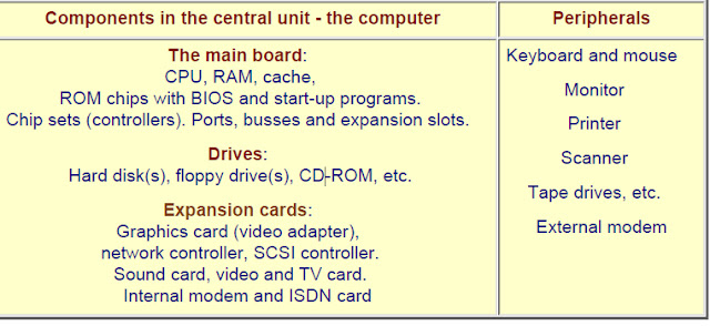
The PC consists of a central unit (referred to as the computer) and various peripherals. The computer is a box, which contains
most of the working electronics. It is connected with cables to the peripherals.
On these pages, I will show you the computer and its components. Here is a picture of the computer:
Here
Here is a list of the PC components. Read it and ask yourself what the words mean.. Do you recognize all these components?

Types of Interrupts

Types of Interrupts

Level-triggered

A Level-triggered interrupt is an interrupt signalled by maintaining the interrupt line at a high or low level. A device wishing to signal a Level-triggered interrupt drives the interrupt Request line to its active level (high or low), and then holds it at that level until it is serviced. It ceases asserting the line when the CPU commands it to or otherwise handles the condition that caused it to signal the interrupt.

Typically, the processor samples the interrupt input at predefined times during each bus cycle such as state T2 for the Z80 microprocessor. If the interrupt isn't active when the processor samples it, the CPU doesn't see it. One possible use for this type of interrupt is to minimize spurious signals from a noisy interrupt line: a spurious pulse will often be so short that it is not noticed.
Multiple devices may share a level-triggered interrupt line if they are designed to. The interrupt line must have a pull-down or pull-up resistor so that when not actively driven it settles to its inactive state. Devices actively assert the line to indicate an outstanding interrupt, but let the line float (do not actively drive it) when not signalling an interrupt. The line is then in its asserted state when any (one or more than one) of the sharing devices is signalling an outstanding interrupt.
Level-triggered interrupt is favored by some because it is easy to share the interrupt Request line without losing the interrupts, when multiple shared devices interrupt at the same time. Upon detecting assertion of the interrupt line, the CPU must search through the devices sharing the interrupt Request line until one who triggered the interrupt is detected. After servicing this device, the CPU may recheck the interrupt line status to determine whether any other devices also needs service. If the line is now de-asserted, the CPU avoids checking the remaining devices on the line. Since some devices interrupt more frequently than others, and other device interrupts are particularly expensive, a careful ordering of device checks is employed to increase efficiency. The original PCI standard mandated level-triggered interrupts because of this advantage of sharing interrupts.
There are also serious problems with sharing level-triggered interrupts. As long as any device on the line has an outstanding request for service the line remains asserted, so it is not possible to detect a change in the status of any other device. Deferring servicing a low-priority device is not an option, because this would prevent detection of service requests from higher-priority devices. If there is a device on the line that the CPU does not know how to service, then any interrupt from that device permanently blocks all interrupts from the other devices.

Edge-triggered

An edge-triggered interrupt is an interrupt signalled by a level transition on the interrupt line, either a falling edge (high to low) or a rising edge (low to high). A device, wishing to signal an interrupt, drives a pulse onto the line and then releases the line to its inactive state. If the pulse is too short to be detected by polled I/O then special hardware may be required to detect the edge.

Multiple devices may share an edge-triggered interrupt line if they are designed to. The interrupt line must have a pull-down or pull-up resistor so that when not actively driven it settles to one particular state. Devices signal an interrupt by briefly driving the line to its non-default state, and let the line float (do not actively drive it) when not signalling an interrupt. This type of connection is also referred to as open collector. The line then carries all the pulses generated by all the devices. (This is analogous to the pull cord on some buses and trolleys that any passenger can pull to signal the driver that they are requesting a stop.) However, interrupt pulses from different devices may merge if they occur close in time. To avoid losing interrupts the CPU must trigger on the trailing edge of the pulse (e.g. the rising edge if the line is pulled up and driven low). After detecting an interrupt the CPU must check all the devices for service requirements.
Edge-triggered interrupts do not suffer the problems that level-triggered interrupts have with sharing. Service of a low-priority device can be postponed arbitrarily, and interrupts will continue to be received from the high-priority devices that are being serviced. If there is a device that the CPU does not know how to service, it may cause a spurious interrupt, or even periodic spurious interrupts, but it does not interfere with the interrupt signalling of the other devices. However, it is fairly easy for an edge triggered interrupt to be missed - for example if interrupts have to be masked for a period - and unless there is some type of hardware latch that records the event it is impossible to recover. Such problems caused many "lockups" in early computer hardware because the processor did not know it was expected to do something. More modern hardware often has one or more interrupt status registers that latch the interrupt requests; well written edge-driven interrupt software often checks such registers to ensure events are not missed.
The elderly Industry Standard Architecture (ISA) bus uses edge-triggered interrupts, but does not mandate that devices be able to share them. The parallel port also uses edge-triggered interrupts. Many older devices assume that they have exclusive use of their interrupt line, making it electrically unsafe to share them. However, ISA motherboards include pull-up resistors on the IRQ lines, so well-behaved devices share ISA interrupts just fine.

Hybrid

Some systems use a hybrid of level-triggered and edge-triggered signalling. The hardware not only looks for an edge, but it also verifies that the interrupt signal stays active for a certain period of time.

A common use of a hybrid interrupt is for the NMI (non-maskable interrupt) input. Because NMIs generally signal major – or even catastrophic – system events, a good implementation of this signal tries to ensure that the interrupt is valid by verifying that it remains active for a period of time. This 2-step approach helps to eliminate false interrupts from affecting the system.

Message-signaled

Main article: Message Signaled Interrupts

message-signalled interrupt does not use a physical interrupt line. Instead, a device signals its request for service by sending a short message over some communications medium, typically a computer bus. The message might be of a type reserved for interrupts, or it might be of some pre-existing type such as a memory write.
Message-signalled interrupts behave very much like edge-triggered interrupts, in that the interrupt is a momentary signal rather than a continuous condition. Interrupt-handling software treats the two in much the same manner. Typically, multiple pending message-signalled interrupts with the same message (the same virtual interrupt line) are allowed to merge, just as closely spaced edge-triggered interrupts can merge.
Message-signalled interrupt vectors can be shared, to the extent that the underlying communication medium can be shared. No additional effort is required.
Because the identity of the interrupt is indicated by a pattern of data bits, not requiring a separate physical conductor, many more distinct interrupts can be efficiently handled. This reduces the need for sharing. Interrupt messages can also be passed over a serial bus, not requiring any additional lines.
PCI Express, a serial computer bus, uses message-signalled interrupts exclusively.

Doorbell

In a push button analogy applied to computer systems, the term doorbell or doorbell interrupt is often used to describe a mechanism whereby a software system can signal or notify a computer hardware device that there is some work to be done. Typically, the software system will place data in some well known and mutually agreed upon memory location(s), and "ring the doorbell" by writing to a different memory location. This different memory location is often called the doorbell region, and there may even be multiple doorbells serving different purposes in this region. It's this act of writing to the doorbell region of memory that "rings the bell" and notifies the hardware device that the data is ready and waiting. The hardware device would now know that the data is valid and can be acted upon. It would typically write the data to a hard disk drive, or send it over a network, or encrypt it, etc.

The term doorbell interrupt is usually a misnomer. It's similar to an interrupt because it causes some work to be done by the device, however the doorbell region is sometimes implemented as a polled region, sometimes the doorbell region writes through to physical device registers, and sometimes the doorbell region is hardwired directly to physical device registers. When either writing through or directly to physical device registers, this may, but not necessarily, cause a real interrupt to occur at the device's central processor unit (CPU), if it has one.
Doorbell interrupts can be compared to Message Signaled Interrupts, as they have some similarities..

Hardware Interrupts

Hardware Interrupts
The adapter or unit on the I/O bus uses the interrupt to signal request to send or receive data. An interrupt
signal is like a door bell. The unit signals by applying a voltage to one of the wires in the bus - an IRQ.
When the CPU acknowledges the signal, it knows that the unit wants send or receive data, or is finished.
The advantage of IRQ's is that the CPU can manage other tasks, while an adapter "massages" its data.
When the adapter has finished its task, it will report to the CPU with a new IRQ.
As an example, let us see how keyboard data are handled. The keyboard send bits, serially, through the
cable to the keyboard controller. The controller organizes them in groups of 8 (one byte). Every time it has a
byte, it sends an IRQ to the I/O bus. The IRQ controller asks the CPU permission to use the bus, to send
the byte to wherever. The IRQ controller reports back to the keyboard controller, giving clearance to send
the next character (byte):
A Guide to Adapters and I/O units.


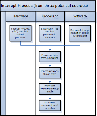
hardware interrupt is an electronic alerting signal sent to the processor from an external device, either a part of the computer itself such as a disk controller or an externalperipheral. For example, pressing a key on the keyboard or moving the mouse triggers hardware interrupts that cause the processor to read the keystroke or mouse position. Unlike the software type (below), hardware interrupts are asynchronous and can occur in the middle of instruction execution, requiring additional care in programming. The act of initiating a hardware interrupt is referred to as an interrupt request (IRQ).
software interrupt is caused either by an exceptional condition in the processor itself, or a special instruction in the instruction set which causes an interrupt when it is executed. The former is often called a trap or exception and is used for errors or events occurring during program execution that are exceptional enough that they cannot be handled within the program itself. For example, if the processor's arithmetic logic unit is commanded to divide a number by zero, this impossible demand will cause a divide-by-zero exception, perhaps causing the computer to abandon the calculation or display an error message. Software interrupt instructions function similarly to subroutine calls and are used for a variety of purposes, such as to request services from low level system software such as device drivers. For example, computers often use software interrupt instructions to communicate with the disk controller to request data be read or written to the disk.
Each interrupt has its own interrupt handler. The number of hardware interrupts is limited by the number of interrupt request (IRQ) lines to the processor, but there may be hundreds of different software interrupts.

Overview[edit source | editbeta]

Hardware interrupts were introduced as a way to reduce wasting the processor's valuable time in polling loops, waiting for external events. They may be implemented in hardware as a distinct system with control lines, or they may be integrated into the memory subsystem.
If implemented in hardware, an interrupt controller circuit such as the IBM PC's Programmable Interrupt Controller (PIC) may be connected between the interrupting device and the processor's interrupt pin to multiplex several sources of interrupt onto the one or two CPU lines typically available. If implemented as part of the memory controller, interrupts are mapped into the system's memory address space.
Interrupts can be categorized into these different types:
  • Maskable interrupt (IRQ): a hardware interrupt that may be ignored by setting a bit in an interrupt mask register's (IMR) bit-mask.
  • Non-maskable interrupt (NMI): a hardware interrupt that lacks an associated bit-mask, so that it can never be ignored. NMIs are used for the highest priority tasks such as timers, especially watchdog timers.
  • Inter-processor interrupt (IPI): a special case of interrupt that is generated by one processor to interrupt another processor in a multiprocessor system.
  • Software interrupt: an interrupt generated within a processor by executing an instruction. Software interrupts are often used to implement system calls because they result in a subroutine call with a CPU ring level change.
  • Spurious interrupt: a hardware interrupt that is unwanted. They are typically generated by system conditions such as electrical interference on an interrupt line or through incorrectly designed hardware.
Processors typically have an internal interrupt mask which allows software to ignore all external hardware interrupts while it is set. Setting or clearing this mask may be faster than accessing an interrupt mask register (IMR) in a PIC or disabling interrupts in the device itself. In some cases, such as the x86 architecture, disabling and enabling interrupts on the processor itself act as a memory barrier; however, it may actually be slower.
An interrupt that leaves the machine in a well-defined state is called a precise interrupt. Such an interrupt has four properties:
  • The Program Counter (PC) is saved in a known place.
  • All instructions before the one pointed to by the PC have fully executed.
  • No instruction beyond the one pointed to by the PC has been executed (that is no prohibition on instruction beyond that in PC, it is just that any changes they make to registers or memory must be undone before the interrupt happens).
  • The execution state of the instruction pointed to by the PC is known.
An interrupt that does not meet these requirements is called an imprecise interrupt.

IRQ's

IRQ's
When you install an expansion board in a slot, it gets connected to the I/O bus. Now the board can send
and receive data. But who regulates the traffic? Who gives clearance to the new controller to send data? It
would appear that data traffic could soon be chaotic.
A Guide to Adapters and I/O units.
To control data traffic on the I/O bus, the concept of IRQ (Interrupt ReQuest) was created. Interrupts are a
fundamental principle in the PC design. There are two types of interrupts: Software Interrupts are used to
call any number of BIOS routines. Hardware Interrupts are the subject of this page.


The internal I/O ports

The internal I/O ports
As mentioned, the USB is going to become the main bus for low-speed devices. But so far we still use the
internal "face" of the ISA bus for a range of purposes. At any PC motherboard you find these:
l   The floppy controller
l   The serial portsl   The parallel port(s)
l   The keyboard controller
They all occupy IRQ's which is a central part of ISA architecture and a pain in the a... Let us take a moment
to look at these ports and controllers.
The serial ports
Serial transmission means to send data from one unit to another one bit at the time. The PC architecture
traditionally holds to RS232 serial ports. The RS-232 standard describes an asynchronous interface. This
means that data only are transmitted when the receiving unit is ready to receive them:
The serial ports are controlled by an UART chip (Universal Asynchronous Receiver Transmitter) like 16550
AFN. This chip receives bytes from the system bus and chops them up into bits. The most common
package is called 8/N/1 meaning that we send 8 bits, no parity bit and finally one stop bit. This way one byte

occupies 9 bits:

The serial ports are controlled by an UART chip (Universal Asynchronous Receiver Transmitter) like 16550
AFN. This chip receives bytes from the system bus and chops them up into bits. The most common
package is called 8/N/1 meaning that we send 8 bits, no parity bit and finally one stop bit. This way one byte
occupies 9 bits:
A Guide to Adapters and I/O units.


The serial transfer is limited to a speed of 115,200 bits per second. The cable can be up to 200 meter long.
The serial ports can be used to connect:
l   The mouse
l   Modems
l   ISDN adapters
l   Printers with serial interface
l   Digital cameras
l   ....
These units are connected to the serial ports using either DB9 or DB15 plugs.
In a few years time all these devices will connect to the USB bus instead.
The parallel port
Parallel transmission means that data are conducted through 8 separate wires - transmitting a full byte in
one operation. This way the parallel transmission is speedier than the serial, but the cabling is limited to
5-10 meters. The cable is fat and unhandy, holding up to 25 wires and the transmission is controlled
according to the Centronics standard.
Most printer manufactories use a 36-pins Amphenol plug, where the PC's parallel port holds a 25-pinned
connector. Hence the special printer cable. To the left you se the 25 pin connector, to the right the 36-pin:
A Guide to Adapters and I/O units.

Other MO drives

Other MO drives
There are other MO drives available. However, they are currently in a quite different price range
than the Zip drives.
In the last four years, we have heard about the LS120 drive and now it is finally available. It is a
Compaq 120 MB standard. It is supposed to replace the regular floppy drives. At the same
time, they read floppy diskettes much faster than the traditional floppy drives.
The LS120 ought to become the new floppy standard, but it has come to late. Soon we will
have the DVD RAM disks which holds from 2.6 GB and up.
Sony has a MO drive called HiFD holding 200 MB on a 3½" floppy disk. It also reads DD and
HD floppies.
Use the LS120 or the HiFD in new PC's - they are cheap and good for backup. The drives use
EIDE interface.

Two types of interface

Two types of interface
The Zip drive exists in different versions:
l   Internal and external
l   For SCSI and to floppy/parallel port
The SCSI model is by far the fastest. That is really good. If your SCSI controller is installed with
Windows 95, you just have to install the drive with two screws and two cables and you are in
business.
The parallel port version is good, because it can be connected to any PC. I have a boot
diskette, which includes a driver plus the program GUEST.EXE. I connect the drive to a parallel
port, and boot with the diskette. Then it is ready to run.
I have the quite fast SCSI version installed in my stationary PC. I use the somewhat slower
parallel port version "in the field."
My latest information is that 5 million Zip drives have been sold. This just about makes it a de
facto standard. The BIOS manufacturers AMI and Phoenix include the floppy version of the
drive in their programs as a boot device. That will eliminate the need for other drivers, and you
An illustrated Guide to Magneto-Optical drives.

The Zip drive

The Zip drive
The Zip drive uses a kind of diskette, which can hold 100 MB. In my opinion, the Zip drive
works excellently. They are stable, inexpensive, and easy to work with. The drives are not the
fastest. One reason is, that they must make two revolutions for each write operation.
I and many others have used Zip drives since they came on the market. This provides us with a
common standard to move large files and to make back-ups. For example, you can use this
drive to install Windows 95 on a computer without a CD ROM and avoid having to insert
numerous floppy disks.
zip drive
The 100 MB Zip disk is borderline size. However, compared to the work I had to do previously,
compressing files with PKZIP onto multiple diskettes, these are very practical.

MO drives

MO drives
Magnetic-Optic drives represent an exciting technology. The media is magnetic, yet very
different from a hard disk. You can only write to it, when it is heated to about 300 degrees
Fahrenheit (The Curie point)
This heating is done with a laser beam. The advantage is that the laser beam can heat a very
minute area precisely. In this manner the rather unprecise magnetic head, can write in
extremely small spots. Thus, writing is done with a laser guided magnet. The laser beam reads
the media. It can detect the polarization of the micro magnets on the media.
MO disks are fast, inexpensive, and extremely stable. They are regarded as almost wear-proof.
They can be written over and over again forever, without signs of wear. The data life span is
said to be at least 15 years. There are many MO drive variations. The most widespread is the
Iomegas Zip drive with the LS120 coming up.
The Zip

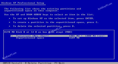
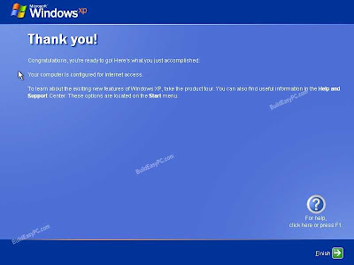
XP INSTALLATION PROCESS

          XP INSTALLATION  PROCESS